You are here: Tools > AKD into KAS > Workbench User Guide > 24 V Auxiliary Supply (X1)

24 V auxiliary supply (X1)

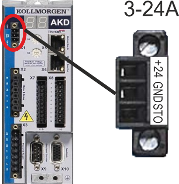
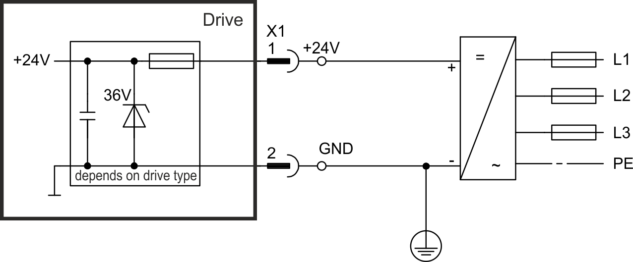
The following diagram describes external 24 VDC power supply, electrically isolated, for example, via an isolating transformer. The required current rating depends on the use of motor brake and option card .


003 to 024, connector X1

Pin

Signal

Description

1

+24

+24 VDC Auxiliary voltage

2

GND

24V Supply GND

3

STO

STO enable (Safe TorqueTorque is the tendency of a force to rotate an object about an axis. Just as a force is a push or a pull, a torque can be thought of as a twist Off)

048, connector X1

Pin

Signal

Description

1

+24 V

+24 VDC Auxiliary voltage

2

GND

24V Supply GND

3

STO +24V

STO+24 VDC Auxiliary voltage

4

STO GND

STO Supply GND

5

STO-Status 1

Safe Torque Off status channel 1

6

STO-EnableEnable signal for the drive, Hardware-Enable with 24V signal to X8, Software-Enable command by setup Software, fieldbus or permanently set. Both are required for enabling the drive. 1

Safe Torque Off enable channel 1

7

STO-Status 2

Safe Torque Off status channel 2

8

STO-Enable 2

Safe Torque Off enable channel 2


Stay Connected with Kollmorgen

Copyright © 2015 Kollmorgen™